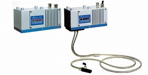
Infrared Multi Analyzer (Moisture/Organic Compound/Film Thickness/Coating Thickness) IM Series
The IM series is multi IR wavelength analyzer utilizing infrared absorption technology for measuring product moisture, organic compound, film thickness, and coating thickness etc. Using maximum ten wavelengths from near-infrared to infrared region, various constituent measurement is available. Also, simultaneous measurement up to four components can be done.
- Supports multiple interfaces.
- Equipped with RS-485(MODBUS), Ethernet (LAN), and analog output.
- High-speed, high-sensitivity, and multiple calculations.
- High-speed and high-sensitivity measurement is enabled by output update interval 28ms, and ideal optical design. Also for calculation, there are 2-color, 3-color ratio calculations, and multiple regression calculation which takes multicomponent variable factor into account and enables optimum condition setting, are available for each calibration curve individual setting.
- Easy maintenance design comes with self-diagnostic function.
- Motor, power supply unit, and lamp etc., design considering easy maintenance for users.
Models
Multi-Analyzer
| Names | Models | |
|---|---|---|
| Mirror Type (Reflection) | For general moisture | IRMA1100□□ |
| For high in moisture | IRMA1200□□ | |
| For trace amount of moisture | IRMA1300□□ | |
| For thickness/Coating (NIR) | IRMA7100□□ | |
| For thin film thickness/Coating(IR) | IRMA7200□□ | |
| Fiber Type (Reflection/Transparent) | General moisture | IRMA2100□□ |
| For high in moisture | IRMA2200□□ | |
| For thickness/Coating | IRMA8100□□ | |
*Fiber-optic is necessary for fiber type.
Infrared Multi Analyzer
| Measuring System | Infrared absorption type | |
|---|---|---|
| Measuring Wavelength | Up to 10 wavelengths | |
| Measuring Component | Up to 4 constituents | |
| Measuring Distance/Diameter | Mirror type: | Measuring distance 300mm (can be installed in 200 to 400mm) Diameter 50×50mm (at measuring distance 300mm) |
| Fiber type: | With lens…φ20/25mm to φ40/100mm Without lens…φ20/15mm to φ50/50mm (transparent is special) | |
| Output Signal | (1) Analog signal: 4 to 20mADC, ±0.2%FS (Load resistance 500Ω or lower) (2) Communication signal: RS-485 (MODBUS)…Standard (3) Ethernet (LAN) *(3) can not be used with RS-485. | |
| Output Update Interval | 28ms | |
| Display/Setting | Data display, set value display, various setting can be key in | |
| Calibration Curve | Linear equation to cubic equation, and multiple regression equation Calibration curve correction function is available (1st to 2nd correction) | |
| No. Of Calibration Curve | 99 (max) | |
| Calculation Function | 2-color and 3-color ratio calculation, multiple regression calculation | |
| Smoothing Processing | 0 to 99.9sec., can be set freely | |
| Calibration | Calibration can be done with checking plate | |
| Self-Diagnosis Function | Contact and communication output at self-diagnosed abnormal conditions | |
| Correction Input Function | Correction of measured data with an external 4 to 20mA DC input (1 input) (Sample temperature correction, others) | |
| Contact Input/Output | Contact input (Di): One function selected from preset, data hold, or the real/smooth switching can be input via the contact input. Contact output (Do): One function selected from the self-diagnosis function (1b) or the high/low alarms (1a) can be output as the contact output. | |
| Working Temperature Range | Working Temperature Range 0 to 50°C (Cooling air is necessary if the working temperature is 45°C or higher. Dry air approx. 30°C or lower for instrumentation is to be used. | |
| Power Supply | 24V DC (Supplied from attachment power supply unit IR-WEP. Support power supply unit: 100 to 120V AC, 47 to 450Hz) | |
| Power Consumption | Approx. 30VA | |
| Connection | Terminal connections (Cable gland) | |
| Case | Aluminum casting | |
| Weight | Approx. 4.3kg | |
Setting Display Unit
| Input Signal | RS-485 (from detector), Max 9 devices can be connected |
|---|---|
| Output Signal | (1) Analog signal: 4 to 20mADC, Three outputs *(Load resistance 500Ω or lower) *For multiple heads, detector No. 1, 2, 3 each one output (2) Communication signal: Specify RS-232C, RS-422A, or RS-485 |
| Output Scaling | Numeric keypad setting (0.1 step) |
| Output Update Interval | Communication output: 28ms×Number of connected detector |
| Display | (1)Measured value display □□□□.□ (Decimal point position can be changed) (2) Head No. CH.No., Parameter display |
| Smoothing T | Setting of smoothing time at smoothing calculation/ T=0.1 to 99.9s |
| Calibration Operation | When output checking plate is inserted, perform calibration by key operation or external contact. |
| Hold/ Preset Operation | Hold/Preset display and output by key operation or external contact. |
| Calibration Curve Correction | Online correction of input calibration curve, Linear equation to quadratic equation correction |
| External Setting Function | Head No. CH.No., Calibration, Hold, Preset can be done. |
| Alarm Function | Contact output (1 output) to HCL terminal when it is out of setting range. |
| Self-Diagnosis | Contact output (1b) at detector self-diagnosed abnormal conditions with lamp indication. |
| Power Supply | 100 to 240V AC 50/60Hz |
| Power Consumption | Max 15VA |
| Working Temperature Range | 0 to 50°C |
| Case | Flame retardant polycarbonate |
| Installation Method | Panel flush-mount |
| Weight | Approx. 0.6kg |
Fiber Unit
| Measuring Distance/Diameter | With lens… | φ20/25mm to φ40/100mm |
|---|---|---|
| Without lens… | φ20/15mm to φ50/50mm | |
| Fiber Length | Standard 1.5m, Max 5m (at reflection fiber) Standard 2m, Max 10m (at transparent fiber) | |
| Fiber Protection | Stainless steel corrugated tube | |
| Minimum Bending Radius | R100mm | |
| Working Temperature Range | 0 to 150°C | |
| Air Purge Function | With lens…without purge function Without lens…5 to 20NL/min | |
| Attachment | Horizontal installation holder, flange holder | |